![]()
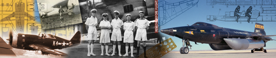
First of all I have to say that the Focke Wulf FLITZER is one of the German WW II. projects. So this Revell 1/72 scale model kit is only some kind of a “what if” airplane – which was neither finished nor flewn. Only a 1:1 wooden model was completed in 1944 and tested in the wind tunnel. The brief – but interestng history of German WW II. era jet plane projects development can be found in this kit’s Instruction manual.

Browsing either the Internet or piles of various publications concerning German jet projects brings more [text] information suitable mainly for historians, but not enough for us – modellers: one would find some more or less similar drawings plus the mentioned wooden model’s b/w photographs.

This kit is really one of those “out of the box” kits you would build quickly and easily during one weekend. Some kind of super detailing and/or shifting closer to the reality is practically impossible, cause you are able to compare neither the shape nor the details of this kit with the real plane. You can only imagine how it could be and follow your feelings. And I went this way too.
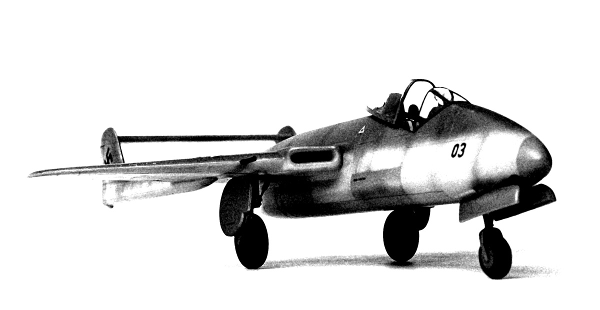
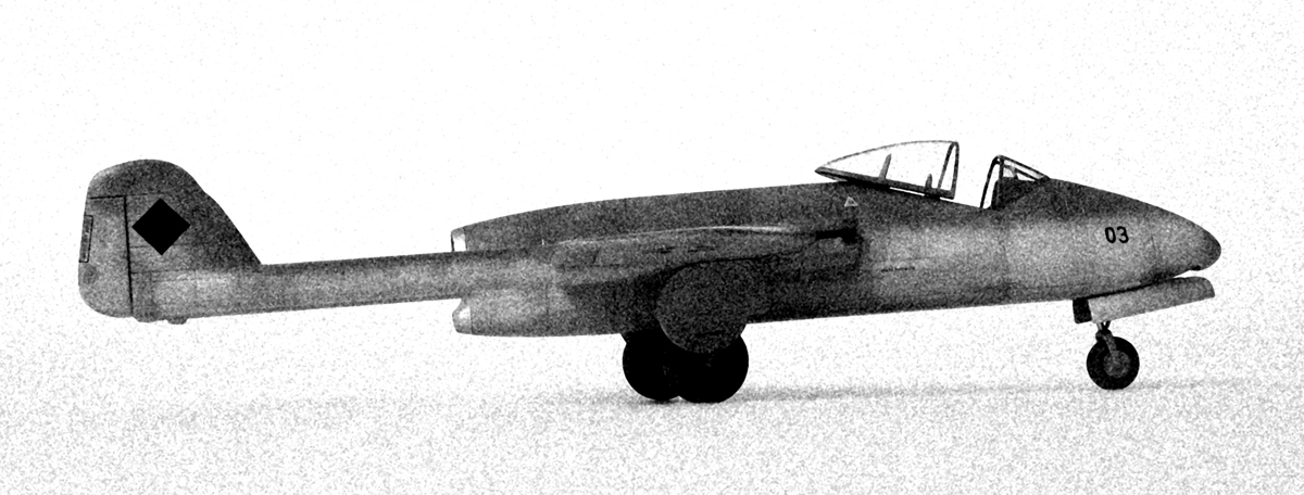
 All upper b/w photographs (of my finished kit) were modified in endeavour to simulate the historical-like shots.
1. Improvements I have made
Wing root & air intakes
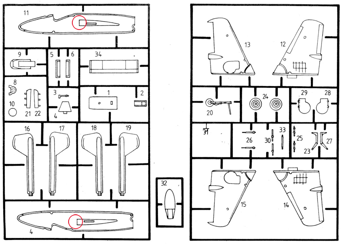
The first thing which I felt improbable was the shape of the area between air intakes and the fuselage, where the wing leading edge transitions into the fuselage. Revell made this junction practically rectangular here. It can be seen in the building instruction diagram below (I am afraid I forgot to make a photograph of the kit prior to reshaping it):

The whole wing leading edge is round-shaped, so it looked better to me to round the wing root portion too. The new shape can be seen here:

Comparing the air intakes with the original FLITZER wooden model you would also feel like Revell made them a little more boxy. Therefore the intakes on my kit were rounded a bit as well – mainly the inner surfaces.
Front undercarriage well
The second place where I felt need of a mild correction is the front landing gear well. When the well is in the proper position inside the fuselage it looks like Revell made its side walls too thick – or the distance between them too small. The situation can be seen on the picture below:

There is no need to worry though – both side walls can be easily removed and replaced with new ones made of a thin styrene material. The replacement can be seen here:

The yellow line depicts the area of connection – the styrene sheets were glued onto the original (modified) model part No. 9 here.

The blue line runs along the inner fuselage shape and the magenta line along the outer one, i.e. the distance between the blue and magenta lines represents the thickness of the fuselage walls (fusalage halves – kit part No. 7 and 11).

The styrene walls were left protruding outward (beyond the magenta line here). Just after the fuselage assembly they were made into their final shape. The excess styrene was removed with a sharp knife and sanded to be smooth. No putty was needed here, only gluing – the walls fit well.
Front undercarriage
Further retouching was done on the front landing gear – it is not necessary though. The front wheel is moulded as one piece with the leg and its actuator. I like these pieces separated if possible. So a brand new upper part of the landing gear was made using metal injection needles and a very thin metal sheet cut into narrow bands. The needles were inserted into one another – the final length of the undercarriage was set as the final step, in order to keep the proper position of the plane – with its tail directed slightly downwards. Similar older jet airplanes like D. H. Vampire and Venom are directed this way (the Revell instruction sheet calls for this posture too).
The front wheel was not fully separated (from the rest of the gear), only a very thin gap was created here using the needle tip as a scriber. Filling this gap with a dark shade of colour enhanced the needed effect. This is a close-up of the front undercarriage parts:

Canopy / or how to make own acetate canopy easy
When my FLITZER was nearly completed it was clear it needed a new canopy. The canopy coming with the kit was too thick and single-piece, thus nearly nothing inside the cockpit could be seen. The new acetate canopy solved this problem. The original canopy was used to make the mock-up first. The materials used in the process of making the negative were plaster (=gypsum), styrene and modelling clay. Then the 5-minutes epoxy was used as a material for the mock-up (positive). I had no vacuum pump on hand so bubbles remained inside the mock-up. Those of them reaching the surface had to be filled (Mr. Surfacer 500 was used and applied by a thin brush) and sanded. The process of making the canopy mock-up can be seen here in a few main steps:

This is the original canopy from the Revell kit filled with modelling clay. Two styrene sheets are attached to it. The modelling clay added to close the “fence”:

Then the liquid gypsum was poured inside. The original canopy was brushed with very thin layer of soap beforehand to make the separation layer (in order not to stick onto the gypsum negative).

Here is the negative – the original canopy was removed after gypsum had hardened enough:

The styrene sheet is added (to create another simple fence):

Great helper again – the modelling clay:

The five minutes epoxy was poured into the mold. Tiny bubbles appeared while mixing its two components – these can be removed using the vacuum (pump).

This is the finished canopy mock-up fixed and ready to be used for a new acetate copy shaping. It is standing fixed on a nail super-glued into the opening (drilled) from below:

The pre-heated acetate sheet (using the stove gas flame) was pulled vertically down by hands. Simple and quick method which needed several attempts to find the proper combination of temperature (of the acetate), pulling force, direction and distance. Or simply said – the skill.
Please note: The heated acetate sheet and/or stove gas flame can hurt you. So please use proper protection – for instance some older (leather) ski gloves.
This is the result prior to cutting out the finished canopy:

The finished canopy was divided into (two) separate pieces then. Both were masked and airbrushed to create framing and dipped into the Future wax for higher shine and durability for further handling. The rear canopy piece was attached onto the sliding base plate. It was fitted with an armour plate (which would shelter the pilot’s head eventually), but of course – all of this is only a speculation.

Pilot’s Seat
You can also see my attempt to improve the pilot’s seat here. The original Revell seat was used and upgraded a bit to evoke the ejector seat. This is another speculation whether or not was the real FLITZER equipped with an ejector seat at all. If yes, it could most probably be the type which was used for instance within the Dornier Do-335 or similar.

So, I think it is enough for this time, having written everything about building and optional altering (or upgrading if you want) of this interesting kit. This article became too long, so it was divided. The second part (Building the FLITZER, part II.) will follow with Colors and painting. You will be also able to find more shots of my finished Flitzer model there.
For more finished model-kits please see the Built Kits category. If you enjoyed this post, I’d be very grateful if you’d help it spread by sharing it on Facebook.
Model, Images and Text Copyright © 2011 by Marcel Meres.
Hmm, hmm,hmm……… fajné
po dovolenke bude aj pokračovanie, už som ho začal písať
Liked your build very much and the panelling effect of the paint job. I use a similar system for replicating an actetate canopy but cannot understand why you went to the trouble of making a canopy mock up. I use the kit canopy direct and it never warps if you do not make repetitive moulds. I allow the polystyrene canopy to cool before attempting another draw. I have to admit I use very thin thermoforming acetate on 1:72 models so heating and cooling are a matter of seconds.
Hi Aldo,
many thanks for all your hints!
I have been trying to make the acetate canopy (for my Flitzer) for the first time. So I wanted to save the original Revell canopy for sure. Therefore I made the copy (the gypsum mock-up) and experimented with it rather than with the original one.
I thought I would damage the original canopy by heat or so. I also worried that the new acetate canopy would be too large or wide – with addition of the acetate wall thickness. I have to buy thinner thermoforming material as you advise. I’ll try your simpler way then. Thanks a lot again!
If it helps, I use the acetate you find at stationers used for binding folders. The front cover is the transparent plastic which softens very fast when you apply a heat gun to it and within seconds, you can remove the cast canopy from the kit original to trim. I have very very rarely had an original damaged but you are correct to go about it the safe way. Thank you for sharing a very nicely finished model! Someday I will get around to building mine.
Thanks for the detailed and valuable advice Aldo. As the beginner in acetate-forming process I appreciate any advisory words. And hopefully – our debate can be helpfull for anyone else too…
Hi all,
Is there any way I can purchase one of your canopies? I have been building this kit and lost the canopy. I contacted both Revell and Revell Germany for one but because the kit went discontinued in 2001, no replacement parts are available. I will even take the original canopy if a vac form one is not available. Thanks!!
Don
Hi Don!
I have saved one vac-formed canopy here in my drawer. It is one-pieced and cut out. I also foud the original Revell canopy inside my bin – I noticed one (barely visible) cut on its top but it can be polished (hopefully) and used too… I would send both canopies to you for free – I need only the postage fee to be covered. Please send me your address and I will see the postage then. Marcel Meres